2 Position 6 Pin Switch Wiring Diagram
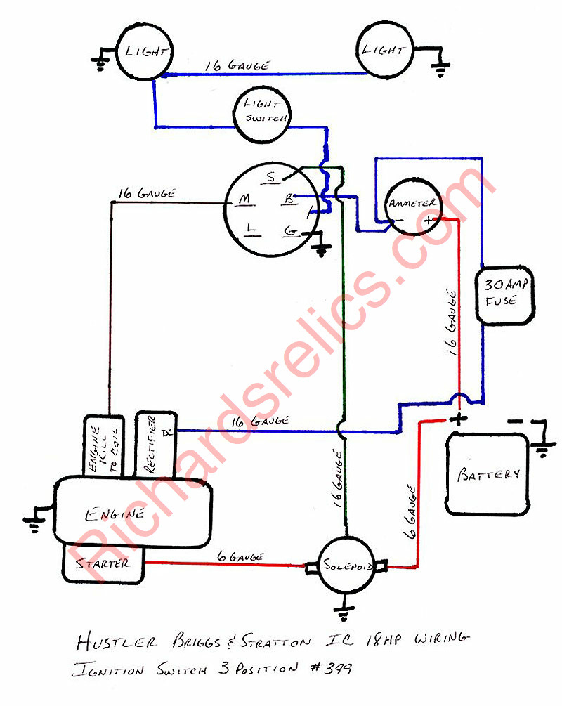
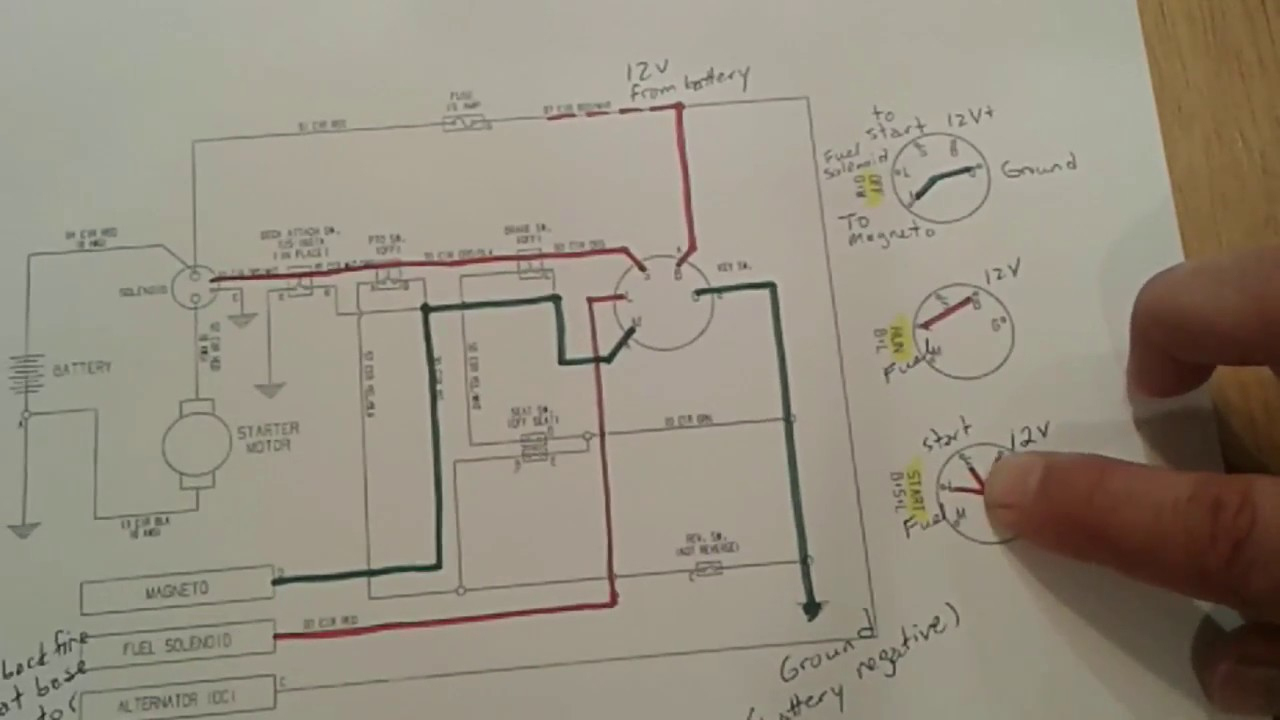
Two pictures are attached - the old wiring into the old ignition and the new ignition. Old ignition had three connections: -IGN. -ST. -BAT. There were four wires going into the old ignition - here is what I believe they connect to: -green - volt meter.
craftsman 7 terminal ignition switch wiring diagram
7 Prong Ignition Switch Wiring Diagram. The seven-prong ignition switch is also common with lawnmowers. It's easy to install, and the wiring is similar to that of 5, and 6-prong ignition switches. If you are having issues with the wiring, check the user manual or hire a professional.
5 Pin Ignition Switch Wiring Diagram
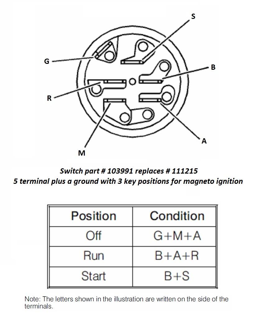
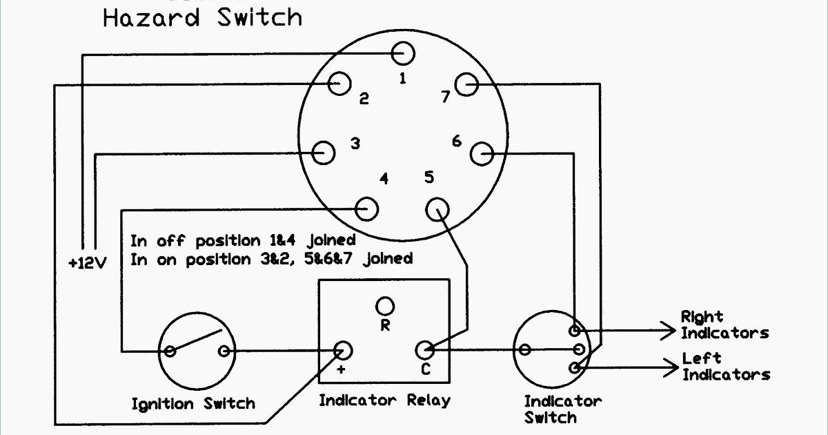
Understanding the wiring diagram for a 7 prong ignition switch is essential for troubleshooting, repairing, or replacing the switch. A 7 prong ignition switch typically consists of seven terminals or prongs labeled with different letters, such as B, M, S, I, R, A, and C. Each terminal has a specific function and connects to different parts of.
7 Prong Ignition Switch Wiring Diagram Wiring Harness Diagram
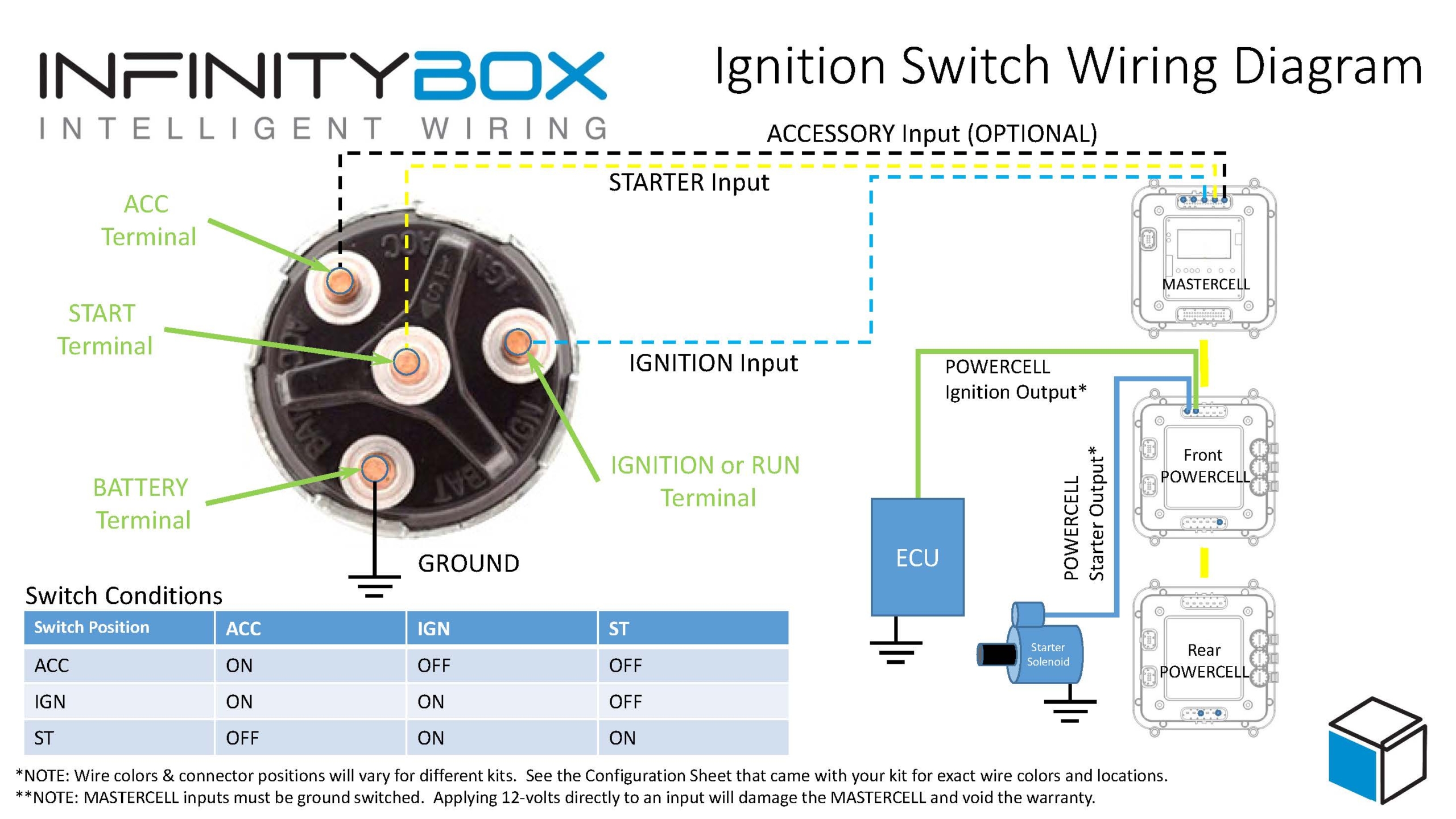
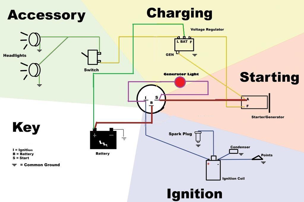
Step 12: Attach the Ignition Wire. Attach the ignition wire to the "IGN" terminal of the vehicle's ignition switch. The central terminal serves the car's ignition, wipers, accessories, and other operating features. It is essentially the default "run" position of the ignition switch.

7 Prong Lawn Mower Ignition Switch Wiring Diagram
Prong Ignition Switch Diagram: A Comprehensive Guide. Understanding the wiring and connections of a 7-prong ignition switch is crucial for anyone working with automotive electrical systems. The ignition switch is an essential component that controls the flow of electricity from the battery to the starter motor, allowing the engine to start and run.

Ignition Switch 3497644 Wiring Diagram Previous Wiring Diagram
Step 1: Obtain a circuit diagram. Step 2: Locate all components that need wiring. Step 3: Connect the switch to ground. Step 4: Connect the switch to the Solenoid. Step 5: Wire the magneto to the switch. Step 6: Provide voltage by connecting the battery. Step 7: Connect the accessories/ lights.